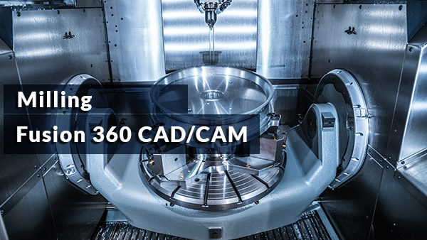

As we learn how to use technology in this way, we unlock the potential of computer aided manufacturing (CAM). This is the case when we use digital data to create complex tool motions. But to compete in the future, you’ll need to connect and automate design and manufacturing processes.Ĭomputers can handle complex tasks that are time consuming or in some cases impossible for the human mind. The “throw-it-over-the-wall” approach to product development worked well enough in the past.

Manufacturers are under more pressure than ever to deliver better products faster, at lower cost, and with less waste. Looking for Autodesk Fusion 360 certification prep courses? Check out additional learning resources to help you uplevel your skills: Sharing your Autodesk Credential can signal to hiring managers that you’ve got the right skills for the job and you’re up on the latest industry trends like generative design. Want to take your learning to the next level? Complete the Autodesk CAD/CAM for Manufacturing Specialization, and you’ll unlock an additional Autodesk Credential as further recognition of your success! The Autodesk Credential comes with a digital badge and certificate, which you can add to your resume and share on social media platforms like LinkedIn, Facebook, and Twitter. We’ll wrap up this course by creating a full CNC program for a part, simulating it, and exporting it to G-code. In this course, we explore how to rough and finish geometry that requires tool motion in X, Y, and Z simultaneously, learning how to finish even the finest of details. For the bottom set up again use the stock from previous setup and same XY origin.As our machining geometry gets more complicated, Autodesk® Fusion 360™ is up to the task! With a host of standard and adaptive toolpaths we can rapidly remove material from even the most complicated 3d parts. Now dowels in the spoil board connected to the top of the stock will position the part for the bottom operations.

These will drill down into the spoil board. Create the drill tool path from the sketch points. So if your XY origin was on the bottom left corner in the top setup and you flip along the X axis the XY origin will be at the top left corner in the spoil board setup. Keep the XY origin at the same place on the stock but z starts at the bottom of the stock next to the spoil board. The part is flipped 180 along an axis so the stock and sketch points are flipped too. Now you need to add a spoil board setup to receive dowel holes from the sketch points. Be sure and use tabs so the remaining stock is attached to the part. In your top setup do all your tool paths and then add a drill tool path at the sketch points. The easiest way is to create a sketch on the top surface of the part and create at least two sketch points where you will drill dowel holes in the stock (not the part).


 0 kommentar(er)
